TM 1-1520-238-23
3-164
3.45.
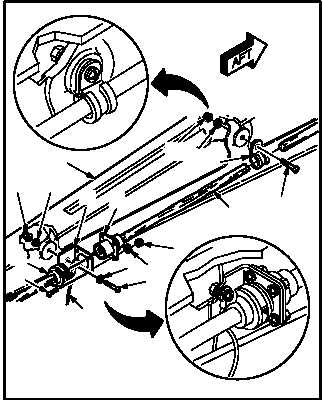
TAIL LANDING GEAR TRAILING ARMS REMOVAL/INSTALLATION – continued
e. Install wire harness (12) on trailing arm (5).
(1) Install screw (19) through washer (21), bond-
ing strap (22), and bracket (18).
(2) Hold screw (19). Install washer (21) and nut
(20).
(3) Perform
electrical
bond
check
(TM 55-1500-323-24).
(a) Bond shall be 0.0025 OHMS or less. Use
ohmmeter.
(4) Seal bonding area. Use sealing compound
(item 178, App F).
(5) Aline receptacle J760 (14) with bracket (18).
(6) Install four screws (15) through bracket (18).
(7) Hold four screws (15). Install washers (17)
and nuts (16).
(8) Attach connector P760 (13) to receptacle
J760 (14).
(9) Install clamp (26) and screw (23).
(10) Hold screw (23). Install washer (25) and nut
(24).
f. Inspect (QA).
g. Install shock strut (para 3.38).
h. Install fork (para 3.43).
i. Install actuating cylinder (para 3.32).
j. Install wheel and axle (para 3.46 or 3.49).
k. Remove tripod jack (para 1.69).
END OF TASK
21
19
12
25
23
24
26
14
18
13
5
M04-0038-14
22
20
16
17
15
21
RIGHT SIDE