TM 1-1520-238-23
Change 1
3-199
3.56.
PILOT BRAKE MASTER CYLINDERS REMOVAL/INSTALLATION – continued
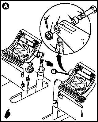
NOTE
Directional control pedals are shown with
protective covers removed.
b. Remove master cylinder assembly (1) from
directional control pedal (2).
(1) Remove and discard cotter pin (3).
(2) Hold bolt (4). Remove self-locking nut (5).
(3) Remove bolt (4) and sleeve bushing (6).
(4) Remove cylinder (1) from pedal (2).
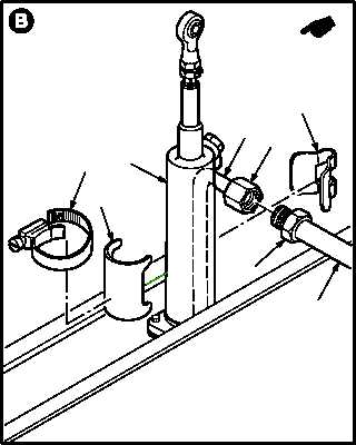
c. Remove nonmetal hose assembly (7) from
brake tube (8).
(1) Hold tube fitting (9). Remove tube coupling
nut (10). Use pail to catch hydraulic fluid
spills.
(2) Remove hose (7) from tube (8).
d. Remove tube supports (11) and (12) from cyl-
inder (1).
(1) Remove hose clamp (13) from supports (11)
and (12).
(2) Remove supports (11) and (12) from cylinder
(1) and tube (8).
GO TO NEXT PAGE
3
5
2
6
4
1
VIEW ROTATED
M04-2746-2A
M04-2746-3A
11
8
1
12
13
9
10
7