TM 1-1520-238-23
2-655
2.180.
TRANSPARENT CREW PROTECTION ARMOR BARRIER REPLACEMENT – continued
e. Install removed components of pilot and CPG
severance device on both sides of transpar-
ent barrier (para 12.77).
(1) Tighten line connections and mounting hard-
ware finger tight. Do not complete system
connections at this time.
CAUTION
To prevent damage to transparent barri-
er, do not over tighten attaching hard-
ware. Standard torques are in
TM 1-1500-204-23.
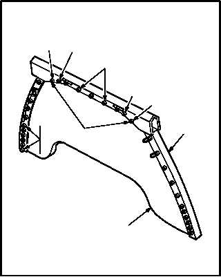
f. Complete installation of barrier (26) in struc-
ture (2).
(1) Install 8 screws (9), 2 screws (36), screws
(35), 12 washers (8), and nuts (7) on forward
side of barrier (26).
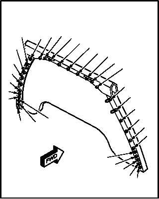
(2) Tighten attaching hardware. Use sequence
chart.
(3) Remove protective tape from structure (2)
and barrier (26).
GO TO NEXT PAGE
M04-3437-10
9
7
8
9
35
36
35
9
2
7
8
26
M04-3437-11
T
V
X
R
P
N
L
J
H
F
D
ZAB AD
A
B
CAE
AC
AA
E
G
I
K
M
O
Q
S
U
WY
SCREW TIGHTENING
SEQUENCE CHART