TM 1-1520-238-23
7-116
Change 9
7.33.
DIRECTIONAL SERVOCYLINDER INSTALLATION – continued
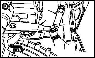
h. Install link (22) on control arm (23).
(1) Install bolt (24) in arm (23) and link (22).
(2) Check fit of self-retaining bolt (24) (para
11.1).
(3) Install nut (25).
i. Torque nut (25) 30 to 45 INCH-POUNDS.
(1) Hold bolt (24). Torque nut (25) to 30 INCH-
POUNDS. Use torque wrench.
(2) Increase torque to aline cotter pin hole, but do
not exceed 45 INCH-POUNDS.
(3) Install new cotter pin (26).
NOTE
If ground cable is installed on helicopter,
go to step j. If not, go to step m.
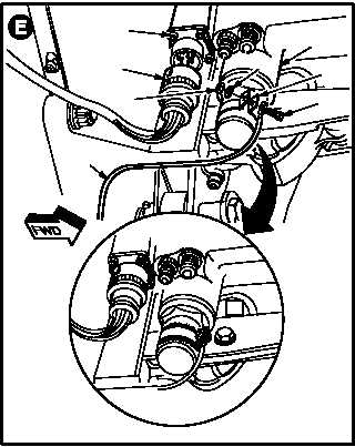
j. Install cable (27) on servocylinder (3).
(1) If installing a new servocylinder, aline new
clamp (28) on servocylinder (3). If reinstalling
servocylinder, use existing clamp (28).
(2) Install screw (29) through cable (27), clamp
(28), washer (30), and nut (31).
k. Perform electrical bond check.
(TM 55-1500-323-24).
(1) Bond shall not exceed 1.0 OHMS. Use ohm-
meter.
l. Apply sealing compound over screw (29),
washer (30), nut (31), and around edges of
clamp (28). Use sealing compound (item 175,
App F).
m. Attach connector P224 (32) to receptacle
(L36)J224 (33).
GO TO NEXT PAGE
M04-780-4
22
23
25
26
24
33
32
27
M04-780-5
3
29
31
30
28


