TM 1-1520-238-23
Change 8
7-117
7.33.
DIRECTIONAL SERVOCYLINDER INSTALLATION – continued
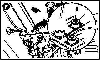
n. Attach connector (L36)P223 (34) to receptacle
J223 (35).
o. Attach connector (L36)P215 (36) to receptacle
J215 (37).
p. Lockwire connector P223 (34) to connector
P215 (36).
(1) Install safety wire with nonmetallic tubing
(anti-chafe), from the barrel of connector
(P215) (36), and attach safety wire to connec-
tor barrel (P223) (34). Use wire (item 222,
App F) and tubing (item 213A, App F).
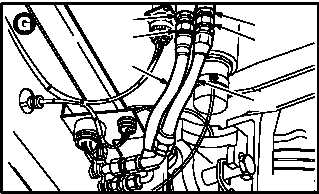
q. Install primary pressure hose (38) on adapter
(39).
(1) Lubricate threads on adapter (39). Use clean
hydraulic fluid (item 92, App F).
(2) Install nut (40) on adapter (39).
r. Install primary return hose (41) on adapter
(42).
(1) Lubricate threads on adapter (42). Use clean
hydraulic fluid (item 92, App F).
(2) Install nut (43) on adapter (42).
s. Inspect (QA).
t. Bleed primary and utility hydraulic systems
(para 1.35).
u. Service primary and utility hydraulic systems
(para 1.34).
v. Perform directional flight controls rigging
maintenance
operational
check
(TM 1-1520-238-T).
w. Perform linear variable differential transducer
(LVDT) adjustment (para 11.216).
x. Perform primary and utility hydraulic systems
maintenance
operational
checks
(TM 1-1520-238-T).
y. Install fairings L540 and L546 (para 2.2).
END OF TASK
M04-780-9A
37
35
34
36
RO%
TATED
VIEW
M04-780-6
42
43
39
40
38
41