TM 1-1520-238-23
Change 6
7-157
7.42.
COLLECTIVE SERVOCYLINDER INSTALLATION – continued
q. Install utility pressure tube (48) on adapter
(49).
(1) Lubricate threads on adapter (49). Use clean
hydraulic fluid (item 92, App F).
(2) Install nut (50). Use crowfoot.
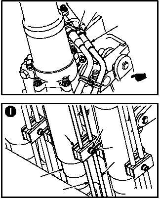
r. Install tube clamp (51). Torque screw (52) to 23
INCH-POUNDS.
(1) Position inner half of clamp (51) between ser-
vocylinder (3) and tubes (45) and (48).
(2) Position outer half of clamp (51) over tubes
(45) and (48). Aline mounting hole.
(3) Install screw (52) through washer (53) and
clamp (51).
(4) Torque screw (52) to 23 INCH-POUNDS. Use
hexagon screwdriver and torque wrench.
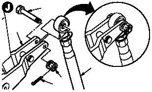
s. Install rod end (54) to control arm (55).
(1) Install bolt (56) through arm (55) and rod end
(54).
(2) Check fit of self-retaining bolt (56) (para
11.1).
t. Install and torque nut (57) on bolt (56) 30 to 40
INCH-POUNDS.
(1) Hold bolt (56). Torque nut (57) to 30 INCH-
POUNDS. Use torque wrench.
(2) Increase torque to aline cotter pin hole, but do
not exceed 40 INCH-POUNDS.
(3) Install new cotter pin (58).
GO TO NEXT PAGE
M04-795-18A
49
50
48
M04-795-12
51
3
45
48
52
53
M04-795-14
56
55
5857
54