TM 1-1520-238-23
9-505
9.134.
STABILATOR RELAY BOX DISASSEMBLY/ASSEMBLY – continued
9.134.6. Assembly
a. Install jumper (27) on cover (3).
(1) Install screw (29) through washer (30), jump-
er (27), and cover (3).
(2) Hold screw (29). Install nut (28).
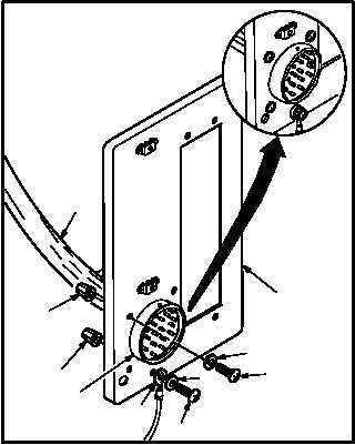
b. Install connector J1 (22) on cover (3).
(1) Position connector (22) on cover (3).
(2) Install four screws (25) through washers (26)
and cover (3).
(3) Hold four screws (25). Install four nuts (24).
(4) Pin
identified
wires
(23)
(TM 55-1500-323-24).
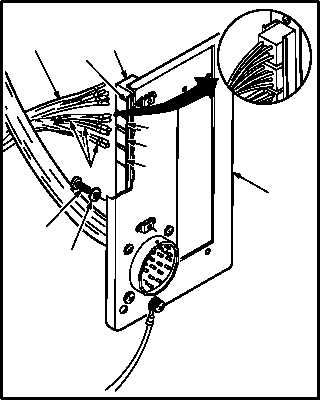
c. Install terminal track (14) on cover (3).
(1) Position track (14) on cover (3).
(2) Install two washers (21) and screws (20).
d. Install terminal junction modules (16), (17),
and/or (18) on terminal track (14).
(1) Install modules (16), (17), and/or (18) (para
9.139).
(2) Pin
identified
wires
(19)
(TM 55-1500-323-24).
e. Install diode terminal (13) on terminal track
(14).
(1) Install terminal (13) (para 9.139).
(2) Pin
identified
wires
(15)
(TM 55-1500-323-24).
GO TO NEXT PAGE
3
26
M04-3614-5
22
30
25
29
27
28
23
24
M04-3614-6
16
13
14
18
19
17
21
20
15
3