TM 1-1520-238-23
10-292
Change 4
10.60.
PILOT FUEL PANEL BRACKET ASSEMBLY REPLACEMENT (AVIM) – continued
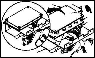
b. Remove electrical component assembly (6)
and cover (9) from bracket assembly (3).
(1) Remove four screws (7), washers (8),
spacers (8.1), and spacers (8.2) (if installed).
(2) Remove cover (9) and component assembly
(6).
10.60.4. Cleaning
a. Clean removed and attaching parts and sur-
faces (para 1.47).
10.60.5. Inspection
a. Check cover and component assembly for
cracks and elongated holes. None allowed.
10.60.6. Installation
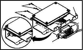
a. Install component assembly (6) and cover (9)
on bracket assembly (3).
(1) Position cover (9) and component assembly
(6) on bracket assembly (3).
(2) Install four screws (7) through washers (8),
cover (9), spacers (8.2) (if removed), compo-
nent assembly (6), and spacers (8.1).
b. Install connectors (1) and (2) on bracket as-
sembly (3).
(1) Install two screws (4) on connector (1).
(2) Install two screws (5) on connector (2).
c. Install pilot fuel panel switches (para 10.58).
d. Install pilot fuel panel boost switch (para
10.57).
e. Install pilot fuel panel crossfeed switch (para
10.56).
f. Inspect (QA).
END OF TASK
7
8
9
6
3
8.1
M04-3906-3A
8.2
9
7
8
6
3
M04-3906-4A
8.1
8.2
3
4
5
2
1
M04-3906-5


