TM 1-1520-238-23
Change 4
11-71
11.10.
LATERAL BELLCRANK AND LATERAL LINKS REMOVAL – continued
11.10.3. Removal
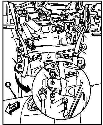
a. Install two cargo straps (1) around swashplate
(2) and main rotor hub (3). Use strap assembly.
b. Tighten cargo straps (1) evenly until weight of
swashplate (2) is supported by hub (3).
c. Remove lateral link (4) from swashplate (2).
(1) Remove sealant from attaching hardware
(para 1.47).
(2) Remove and discard cotter pin (5).
(3) Hold bolt (6). Remove nut (7). Use open end
wrench and socket.
(4) Remove bolt (6), washer(s) (8) (if installed),
and bushing (9).
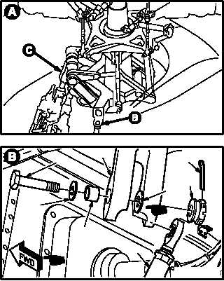
CAUTION
To prevent damage to rigid hydraulic
tubes, ensure upper end of servocylinder
is supported when rod end is discon-
nected from the longitudinal link.
d. Remove lateral servocylinder (10) from lateral
bellcrank (11).
(1) Remove sealant from attaching hardware
(para 1.47).
(2) Remove and discard cotter pin (12).
(3) Hold bolt (13). Remove nut (14). Use open
end wrench and socket.
NOTE
Do not remove nylon washer unless it is
loose or excessively worn.
(4) Remove bolt (13), washer(s) (15) (if re-
quired), nylon washer (16) (if necessary), and
bushing (17).
(5) Remove servocylinder (10).
GO TO NEXT PAGE
5
2
4
9
8
6
7
1
2
3
1
M04-1715-3
M04-1715-1
13
11
15
17
12
14
16
10
M04-1715-2A