TM 1-1520-238-23
11-191
11.38.
PILOT COLLECTIVE STICK SUPPORT REMOVAL/INSTALLATION – continued
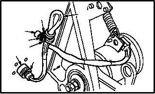
b. Attach connector (A334)P1 (14) to receptacle
J272 (15).
(1) Attach connector (A334)P1 (14) to receptacle
J272 (15).
(2) Install screw (16) through washer (17), clamp
(18), and spacer (19) on wire harness (20).
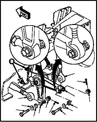
c. Install rod end (8) on bellcrank (2). Torque nut
(4) 30 to 40 INCH-POUNDS.
(1) Aline rod end (8) with bellcrank (2).
(2) Install bolt (11) through washer (12), bushing
(13), bellcrank (2), and rod end (8).
(3) Check fit of self-retaining bolt (11) (para 11.1).
(4) Install nut (10) on bolt (11). Torque nut (10) to
30 INCH-POUNDS. Use torque wrench.
(5) Increase torque to aline cotter pin hole, but do
not exceed 40 INCH-POUNDS.
(6) Install new cotter pin (9).
d. Install rod end (1) on bellcrank (2). Torque nut
(4) 30 to 40 INCH-POUNDS.
(1) Aline rod end (1) with bellcrank (2).
(2) Install bolt (5) through washer (6), bushing
(7), bellcrank (2), and rod end (1).
(3) Check fit of self-retaining bolt (5) (para 11.1).
(4) Install nut (4) on bolt (5). Torque nut (4) to 30
INCH-POUNDS. Use torque wrench.
(5) Increase torque to aline cotter pin hole, but do
not exceed 40 INCH-POUNDS.
(6) Install new cotter pin (3).
GO TO NEXT PAGE
18
19
15
14
20
17
16
M04-3460-6
8
12
11
2
10
9
5
6
2
1
3
4
13
7
M04-3460-4