TM 1-1520-238-23
11-789
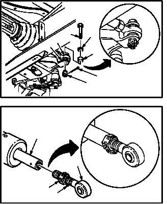
11.178. DIRECTIONAL FEEL SPRING CARTRIDGE INSTALLATION – continued
b. Install rod end (9) on bellcrank (10). Torque nut
(11) to 30 to 40 INCH-POUNDS.
(1) Install bolt (12) through washers (13), bush-
ing (14), bellcrank (10), and rod end (9) to
aline rod end (9) with bellcrank (10).
(2) If rod end (9) alines with bellcrank (10), go to
step b. (11).
(3) If rod end (9) does not aline with bellcrank
(10), go to step b. (4).
(4) Remove and discard lockwire from rod end
(9).
(5) Loosen nut (15) until lock (16) is free of shaft
(17).
(6) Adjust rod end (9) to aline with bellcrank (10).
(7) Hold rod end (9). Tighten nut (15) until lock
(16) engages shaft (17).
(8) Hold rod end (9) Torque nut (15) to 105 INCH-
POUNDS. Use torque wrench and crowfoot.
(9) Install lockwire through nut (15) and lock (16).
Use wire (item 223, App F).
(10) Go to step b.(1).
(11) Check fit of self-retaining bolt (12) (para
11.1).
(12) Install nut (11). Torque nut (11) to 30 INCH-
POUNDS. Use torque wrench.
(13) Increase torque to aline cotter pin hole, but do
not exceed 40 INCH-POUNDS.
(14) Install new cotter pin (18).
GO TO NEXT PAGE
13
12
M04-1814-4
11
18
9
10
14
M04-1814-3
16
17
15
9