TM 1-1520-238-23
Change 5
11-1091
11.260.
DIRECTIONAL F.S. 348 PUSH-PULL ROD WITH GUIDES INSTALLATION – continued
CAUTION
To prevent damage to flight control sys-
tem components, do not use force to
aline bellcrank with bracket or to aline
push-pull rod with bellcrank.
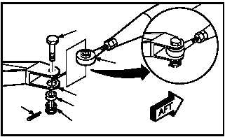
e. Install adjustable end of rod (2) on forward
bellcrank (14). Torque nut (15) 30 to 40 INCH-
POUNDS.
(1) Position rod (2) in bellcrank (14).
(2) Install bushing (16).
(3) Install bolt (17) through bellcrank (14), rod
(2), and bushing (16).
NOTE
If bolt holes do not aline, adjust F.S. 348
push-pull rod (para 11.2).
(4) Check fit of self-retaining bolt (17) (para
11.1).
(5) Install nut (15). Torque nut (15) to 30 INCH-
POUNDS. Use torque wrench.
(6) Increase torque to aline cotter pin hole, but do
not exceed 40 INCH-POUNDS.
(7) Install new cotter pin (19).
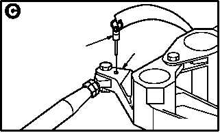
f. Remove -9 rig pin (20) from bellcrank (21).
GO TO NEXT PAGE
M04-1793-4A
17
2
14
16
15
19
20
21
M04-1793-8A