TM 1-1520-238-23
11-1215
11.286.
RIGGING LONGITUDINAL FLIGHT CONTROLS BETWEEN PILOT CYCLIC STICK AND
LONGITUDINAL SERVOCYLINDER – continued
11.286.3. Rigging
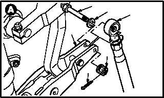
a. Remove F.S. 165 rod end (1) from longitudinal
servocylinder input lever (2).
(1) Remove and discard cotter pin (3).
(2) Remove nut (4).
(3) Remove bolt (5) and washer (6).
b. Enter pilot station (para 1.56). Observe all
safety precautions.
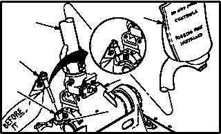
c. Slowly move pilot cyclic stick (7) to aline lon-
gitudinal rig pin hole (8) with rig pin hole (9) in
pilot cyclic stick base (10).
d. Install -9 rig pin (11) in rig pin holes (8) and (9)
in cyclic stick base (10). Use flight control
rigging kit.
e. Install cyclic stick warning cover (12). Use
flight control rigging kit.
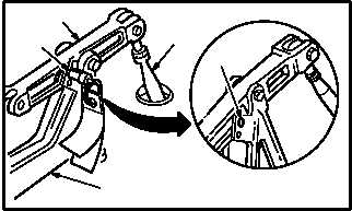
f. Install -9 rig pin (13) in midstroke rig pin hole
(14) in longitudinal F.S. 165 bellcrank (15) and
bracket (16). Use flight control rigging kit.
(1) If -9 rig pin (13) cannot be installed, adjust top
end of F.S. 160 push-pull rod (17) to aline rig
pin holes (14) (para 11.2).
(2) Install -9 rig pin (13).
NOTE
Rig pins installed must be a drop-fit con-
dition in holes. (A slight drag of rig pin is
acceptable.)
g. Verify drop fit of rig pins (11) and (13).
h. Apply external hydraulic power to aircraft
(para 1.72).
GO TO NEXT PAGE
1
M04-3017-7
2
3
4
5
6
12
7
11
8
10
M04-3017-1
9
M04-3017-2
17
14
15
13
16