TM 1-1520-238-23
11-1265
11.295.
RIGGING PILOT AND CPG DIRECTIONAL PEDAL STOP BOLTS – continued
11.295.3. Rigging
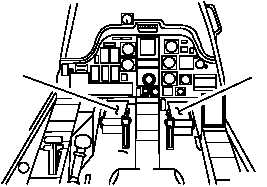
a. Enter pilot station (para 1.56). Observe all
safety precautions.
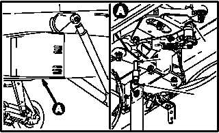
b. Observe pilot directional SPAD (1).
c. Slowly move pilot directional pedals (2) and
(3) to aline rig pin holes (4) in SPAD (1).
d. Install -9 rig pin (5) in SPAD (1). Use flight
control rigging kit.
NOTE
Rig pins installed must be a drop-fit con-
dition in holes. (A slight drag of rig pin is
acceptable.)
e. Verify drop-fit of -9 rig pin (5).
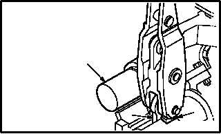
f. Check that lower lever (6) on directional ser-
vocylinder (7) is alined with upper edge of
boss (8) on servocylinder body.
(1) If lever (6) is not alined with upper edge of
boss (8), rig directional flight controls be-
tween pilot pedal and directional servocylind-
er (para 11.294).
(2) If lever (6) is alined with upper edge of boss
(8), go to next step.
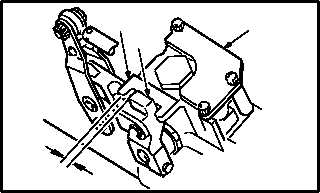
g. Measure and record distance between valve
arm (9) and stop bolt (10) on servocylinder (7).
(1) This is measurement A. Use caliper.
GO TO NEXT PAGE
1
5
M04-3028-1
4
PILOT STATION
M04-3028-2
2
3
8
7
M04-3028-3
6
7
M04-3028-4
A
10
9