TM 1-1520-238-23
11-1272
11.296. RIGGING TAIL ROTOR DIRECTIONAL FLIGHT CONTROLS – continued
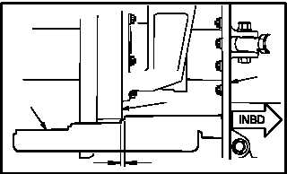
f. Check that rigging tool (2) contacts mast base
(3) and alines with de-ice housing (4).
(1) Install rigging tool (2) between tail rotor gear-
box mast base (3) and swashplate de-ice
housing (4). Use flight control rigging kit.
(2) Hold rigging tool (2) firmly against mast base
(3).
(3) Check that inboard edge of de-ice housing (4)
falls within left pedal position limitations (7)
specified on rigging tool (2).
(4) If inboard edge of de-ice housing (4) does not
aline within limits (7), adjust directional servo-
cylinder rod end (para 11.297).
(5) If adjustment is made to obtain left pedal lim-
its, repeat step b and c.
(6) If left and right pedal limits cannot be ob-
tained by adjusting directional servocylinder
rod end, check rigging of pilot and CPG direc-
tional pedal stop bolts (para 11.295).
(7) If inboard edge of de-ice housing (4) alines
within limits (7), go to next step.
g. Remove rigging tool (2) from between tail ro-
tor gearbox mast base (3) and swashplate de-
ice housing (4).
h. Inspect (QA).
i. Check tail rotor directional controls for free-
dom of movement and 0.0625 INCH clearance
between control rods, bellcranks, and struc-
ture.
(1) Slowly move left pedal full down; check for
freedom of movement and 0.0625 INCH
clearance between rods, bellcranks, and
structure.
(2) Slowly move right pedal full down; check for
freedom of movement and 0.0625 INCH
clearance between rods, bellcranks, and
structure.
GO TO NEXT PAGE
M04-3029-10
3
7
4
2