TM 1-1520-238-T-4
3–13
3–6.
CONTROLS AND INDICATORS
3–6
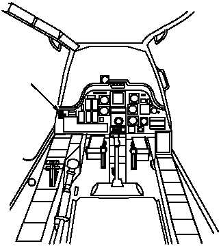
The landing gear system receives mode selects and remote switch inputs from various controls located in the pilot
station (fig. 3–12). Table 3–1 provides a listing of the controls, switches and associated indicators pertaining to the
landing gear system along with a description of their function.
M58-192A
1.
PILOT TAIL WHEEL PANEL
1
Figure 3–12.
Pilot Station
Table 3–1.
Landing Gear System Controls and Indicators
Pilot TAIL WHEEL Panel
SWITCH/INDICATOR
POSITION
FUNCTION
TAIL WHEEL UNLOCK/ LOCK
2–position switch
UNLOCK
Energizes electrical circuit to control tail wheel lock
solenoid.
UNLOCK
De–energizes solenoid in tail wheel lock circuit.
Advisory Light
GREEN
Lights when TAIL WHEEL switch is set to UNLOCK.