TM 1-1520-238-T-4
3–14
3–6.
CONTROLS AND INDICATORS (CONT)
3–6
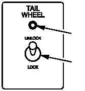
Table 3–1. Landing Gear System Controls and Indicators
M58-193
ADVISORY LIGHT
UNLOCK/LOCK
SWITCH
Pilot TAIL WHEEL Panel
SECTION II.
THEORY OF OPERATION
3–7.
SYSTEM DESCRIPTION
3–7
a. Landing Gear System.
The purpose of the landing gear system is to support the helicopter for all
ground operations and absorb landing shocks. The system consists of two MLGs and one TLG.
(1) The MLG incorporates a trailing arm assembly which is connected at the top of the cross tube
assembly and has a wheel and tire mounted to the bottom. The cross tube assembly provides the major support
structure for the helicopter. A shock strut is mounted on the angled trailing arm assembly to provide
normal/high–impact energy absorption and to provide kneel/erect capability for the helicopter for transportation.
The MLG has a separate brake system for each wheel and is operated by the toe portion of the directional control
pedals in the pilot and CPG crew stations. The parking brake can only be locked from the pilot station but can be
released from the either crew station.
(2) The TLG trailing arm assembly is connected to the tail boom and has a fork and axle assembly with
the wheel and tire mounted at the bottom. The fork provides 360 swiveling capability of the tail wheel. The TLG
fork can be locked at center position manually or hydraulically. The TLG wheel and tire assembly also centers
itself as weight is removed from the wheel.
b. Purpose.
The landing gear system provides support and ground stability for the helicopter fuselage
during taxiing, takeoff, landing, towing and parking. The system dampens and absorbs landing shocks before they
are transmitted to the airframe structure. The TLG swivels, with a wheel centering mechanism, for steering the
helicopter on the ground, or can be locked when desired. The MLG provides mounting for the helicopter wheel
brake assembly.
c. System Operation.
(1) MLG Assembly.
The MLG assembly (fig. 3–13) consists of the cross tube assembly, trailing arm
assembly, shock strut assembly, and the wheel and tire assembly.
(a) Cross Tube Assembly.
The cross tube assembly is a major support structure and provides an
interconnecting pivot for the left and right MLG trailing arms, while transmitting loads from the trailing arm to the
fuselage.