TM 1-1520-238-T-4
3–17
3–7.
SYSTEM DESCRIPTION (cont)
3–7
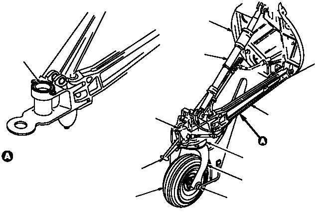
(2) TLG Assembly.
The TLG assembly (fig. 3–14) supports the helicopter during all modes of ground
operations. The TLG extends and compresses which reduces pitching velocities and the possibility of
blade–to–boom contact during tail–low landing impacts. The tail wheel proximity switch provides the pilot the
capability of verifying that the tail fork and wheel assembly are in a locked position.
(a) Trailing Arm Assembly.
The trailing arm assembly provides support to the TLG by absorbing
loads during landing and taxiing and transfers the loads to the shock strut and tail boom structure.
(b) Wheel Centering Mechanism.
The TLG fork and axle assembly provides a housing and socket
for operation of the tail wheel centering mechanism and allows the tail wheel to swivel 360. At takeoff, the wheel
centering mechanism causes the fork assembly to center as helicopter weight is removed from the wheel.
(c) Shock Strut Assembly.
The shock strut assembly absorbs and cushions vertical impact loads
resulting from normal and high–impact landings. The TLG shock strut assembly functions basically the same as
the MLG shock strut. An internal floating diaphragm separates the hydraulic fluid from the nitrogen gas and moves
on–top of the fluid as the shock strut’s upper piston extends and retracts. The hydraulic fluid flows between the
upper piston and cylinder through a poppet valve and orifices which restrict flow. This, in conjunction with the
nitrogen gas compression, dampens helicopter landing shock.
(d) Wheel and Tire Assembly.
The wheel and tire assembly provides the helicopter with the
capability of ground movement during taxi, towing and run–on landing operations.
M58-097A
TRAILING ARM
ASSEMBLY
LOCK HANDLE
SHOCK STRUT
ASSEMBLY
HOUSING
AND SOCKET
TRAILING ARM ASSEMBLY
FORK
ASSEMBLY
AXLE ASSEMBLY
WHEEL CENTERING
MECHANISM
ASSEMBLY
WHEEL AND TIRE
ASSEMBLY
WHEEL LOCK
ACTUATOR
SYSTEM
TAIL BOOM
STRUCTURE
Figure 3–14.
TLG Assembly