TM 1-1520-238-10
2-57
M01-020
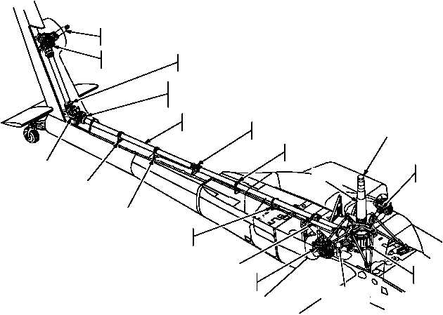
TAIL ROTOR
STATIC MAST
TAIL ROTOR
GEARBOX
FLEXIBLE COUPLING
(TYPICAL)
TAIL ROTOR AND
INTERMEDIATE GEARBOX
COOLING FAN
TAIL ROTOR
DRIVE SHAFTING
HANGER BEARING
(TYPICAL)
ANTIFLAIL
SLEEVE
STATIC
MAST
MAIN ROTOR
DRIVE SHAFT
COOLING FANS
(2)
MAIN
TRANSMISSION
INPUT DRIVE
SHAFTS (2)
NOSE GEARBOX
(2)
APU DRIVE SHAFT
DRIVE SHAFT
DAMPER
DRIVE SHAFT
DAMPER
ANTIFLAIL
SLEEVE
INTERMEDIATE
GEARBOX
Figure 2-32.
Power Train
b. Main Transmission Caution Lights.
Sensors in
the transmission sense adverse conditions which are dis-
played as caution lights (fig 2-44) in the crew stations. The
pilot station has six caution/warning lights: OIL PSI MAIN
XMSN 1, OIL PSI MAIN XMSN 2, OIL HOT MAIN
XMSN 1, OIL HOT MAIN XMSN 2, CHIPS MAIN XMSN,
and OIL PSI ACC PUMP. Activation of any of these lights,
except the OIL PSI ACC PUMP, simultaneously illumi-
nates either MAIN 1, MAIN XMSN 2, or CHIPS MAIN
XMSN on the CPG caution/warning panel.
2.40.3 Rotor Brake.
The rotor brake reduces turn-
around time for aircraft loading and servicing and pre-
vents windmilling of the rotor system during gusty wind
conditions. The rotor brake disc is visible at the aft end of
the transmission.
CAUTION
With rotors turning, do not place the RTR
BK switch in LOCK position.
NOTE
When engaging rotor lock, pause in the
BRAKE position until the RTR BK cau-
tion/warning light has illuminated prior to
placing the switch in the lock position.
The PWR levers will not advance past the
ground idle detent with the rotor brake
switch in the LOCK position.
When operating engines with the rotor
brake locked, monitor the main transmis-
sion temperature. If the transmission
temperature reaches 130 C (266 F), se-
cure operation, or release the rotor brake
and turn the rotors until transmission tem-
perature returns to normal.


