TM 1-1520-238-10
2-62
a. Rotor Blade De-Icing Rotary Switch Opera-
tion.
When the rotor blade de-ice system is operating,
the BLADE ON advisory light on the pilot ANTI-ICE panel
illuminates. The rotary switch above the ON, OFF, and
TEST toggle switch on the pilot ANTI-ICE panel provides
manual override. When the rotary switch is turned out of
the AUTO position, it permits manual control to select
conditions that provide manual heating to the rotor blades
for TRACE, light (LT) and moderate (MOD) icing condi-
tions.
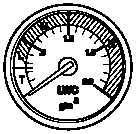
2.43.6 Icing Severity Meter.
An icing severity meter
(fig 2-34) is provided in the right portion of the pilot instru-
ment panel. An aspirated ice detector sensing head, lo-
cated on the doghouse fairing assembly, provides input
signals to a processor. These signals are proportional to
liquid water content (LWC). The signals are sent to the ic-
ing severity meter to give the pilot a numerical indication
of intensity. The meter is marked with both intensities and
categories of ice accumulation. A PRESS TO TEST
switch is provided adjacent to the meter. When this switch
is pressed, the meter pointer will move to 1.5. Both the
BLADE de-ice and the PITOT AD SNSR switches on the
pilot ANTI-ICE panel (fig 2-33) must be on for the ice de-
tector/rate sensor to operate properly.
LWC
PRESS TO TEST
M01-177
Figure 2-34.
Icing Severity Meter and Press-to-Test
Switch
2.44 RAIN REMOVAL.
CAUTION
Windshield wipers should not be oper-
ated when canopies are dry. Scratches
may result.
Two wipers are mounted on the canopy frame to wipe the
two windshields. Both wipers are electrically driven and
are normally controlled by a four-position WSHLD WIPER
rotary switch on the pilot ANTI-ICE panel. The pilot wiper
moves horizontally and the CPG wiper moves vertically.
They receive 28 vdc from the emergency dc bus through
the WSHLD WPR circuit breaker on the pilot overhead cir-
cuit breaker panel. Two speeds, HIGH and LOW may be
selected by the pilot. To return the wipers to their static
position adjacent to the canopy frame, the WSHLD WIP-
ER knob is turned to PARK and held momentarily until the
blades stop. The knob is spring-loaded from PARK to
OFF. The CPG has limited control over the windshield
wipers. Normally, the W WIPER switch on the CPG ANTI-
ICE panel is left in the PLT position. When the switch is set
at CPG, the CPG wiper blade moves at low speed.
2.45 WIRE STRIKE PROTECTION SYSTEM (WSPS).
The WSPS (fig 2-35) consists of six cutter assemblies and
eleven deflectors. An upper cutter assembly is mounted
on top of the pilot station canopy on the left side of the heli-
copter. A lower cutter assembly is mounted on the bottom
of the helicopter, forward of the gun turret bay. A main
landing gear cutter assembly is mounted on each main
landing gear strut by the lower step on the forward side of
the strut. A PNVS cutter assembly is mounted on the top
of the TADS/PNVS. A gun turret deflector and cutter as-
sembly is mounted on the forward side of the gun cradle.
A forward and aft deflector are mounted on each of the pi-
lot and CPG door hinges. An upper wiper deflector as-
sembly is mounted by the upper windshield on the left for-
ward side of the CPG station. A lower wiper deflector
assembly is mounted by the lower windshield on the right
forward side of the CPG station. A tailboom jack pad de-
flector assembly is mounted on the bottom of the tailboom
just forward of the jack pad. A tail landing gear deflector
assembly is mounted on the tail landing gear forward of
the tail wheel. The wire strike protection system is de-
signed to protect the helicopter from wire obstructions at
low levels of flight.


