TM 1-1520-238-23
3-208
3.57.
CPG BRAKE MASTER CYLINDERS REMOVAL/INSTALLATION – continued
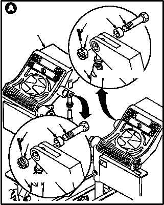
NOTE
Directional control pedals are shown with
protective covers removed.
b. Remove master cylinder assembly (1) from
directional control pedal (2).
(1) Remove and discard cotter pin (3).
(2) Hold bolt (4). Remove self-locking nut (5).
NOTE
7-211521053 bushing used on left brake
only.
(3) Remove bolt (4) and sleeve bushing (6)
(sleeve bushing (7) left brake only).
(4) Remove cylinder (1) from pedal (2).
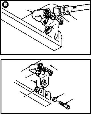
c. Remove brake hose (8) from tube elbow (9).
(1) Remove nut (10) from elbow (9). Use pail to
catch hydraulic fluid spills.
(2) Remove brake hose (8) from elbow (9).
d. Remove bolt (11) and cylinder (1).
(1) Remove and discard cotter pin (12).
(2) Hold bolt (11). Remove self-locking nut (13).
(3) Remove bolt (11), sleeve bushing (14), and
cylinder (1) through access door B60.
GO TO NEXT PAGE
3
M04-131-2
7
4
1
5
2
3
6
4
1
5
VIEW ROTATED
VIEW ROTATED
M04-131-3
8
9
10
M04-131-4
1
12
13
14
11