TM 1-1520-238-23
Change 8
2-268.1
2.76.
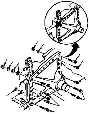
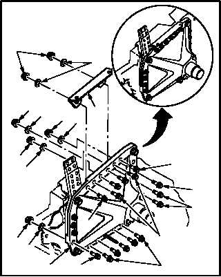
MAIN LANDING GEAR LEFT SHOCK STRUT STRUCTURAL SUPPORT
REMOVAL/INSTALLATION – continued
2.76.6. Installation
NOTE
It may be necessary to add additional
washers to bolts after MWO
1-1520-238-50-46 has been applied.
Use shock strut support wrench set
(figure D-484, App D) to hold nuts as
necessary.
Inspect replacement shock strut sup-
port for guide pins prior to installation.
If support does not have pins installed,
install new pins or reuse pins form old
support.
a. Install support (5) on airframe (2). Torque three
nuts (34), two nuts (31), nut (27), two nuts (24),
nine nuts (17), and nut (14) to 90 INCH-POUNDS.
(1) If required install pins in new support (5) (para
2.77A).
(2) Install bolt (6) and (11) and two bolts (12) on
support (5). Do not tighten.
(3) Install bolt (7), two washers (10), washer (9),
and nut (8) on support (5). Do not tighten.
(4) Install bolts (19) and (20), two washers (22),
and nuts (21) on support (5). Do not tighten.
Use torque wrench adapter.
(5) Install three bolts (33), washers (35), and
nuts (34) on support (5). Torque nuts (34) to
90 INCH-POUNDS. Use torque wrench.
(6) Install angle (29) on support (5).
(a) Position angle (29) on support (5).
(b) Install two bolts (30), washers (32), nuts
(31), and angle (29) on support (5).
Torque nuts (31) to 90 INCH-POUNDS.
Use torque wrench.
(7) Install bolt (26), washer (28), and nut (27) on
support (5). Torque nut (27) to 90 INCH-
POUNDS. Use torque wrench.
(8) Install two bolts (23), washers (25), and nuts
(24) on support (5). Torque nuts (24) to 90
INCH-POUNDS. Use torque wrench.
GO TO NEXT PAGE
5
2
6
12
11
7
8
910
33
35
34
20
2122
19
M04-3744-5A
M04-3744-6A
26
23
16
16
16
24
25
28
27
5
30
13
14
15
18
17
32
31
29


