TM 1-1520-238-23
Change 3
3-55
3.16.
MAIN LANDING GEAR TRAILING ARM ASSEMBLY REMOVAL/INSTALLATION – continued
WARNING
Injury to personnel could occur during
trailing arm installation. Trailing arm
weighs about 50 pounds. Two persons
are required to lift trailing arm on heli-
copter. If injury occurs, seek medical
aid.
CAUTION
Squat switch and target could be dam-
aged during installation of trailing arm as-
sembly. Do not allow trailing arm to hang
straight down. Squat switch and target
are at upper end of trailing arm near
cross tube.
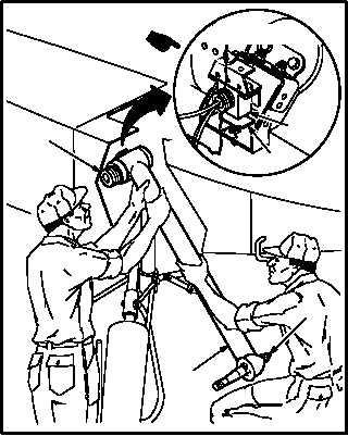
k. Install trailing arm (3) on cross tube (9). Torque
retaining ring (14) to 1200 INCH-POUNDS.
(1) Install trailing arm (3) on tube (9). Do not
damage squat switch (15.1) and target (16).
(2) Install jack pad adapter (para 3.5).
(3) Support trailing arm (3) at jack pad adapter
(32) until shock strut can be installed.
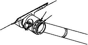
(4) Install spacer ring (15), small side out.
(5) Spray a light coat of lubricant on retaining ring
(14) threads. Use lubricant (item 116, App F).
Install wet.
(6) Install retaining ring (14). Torque to 1200
INCH-POUNDS. Use spanner attachment set
and torque wrench.
(7) Back off retaining ring (14) two holes.
GO TO NEXT PAGE
9
3
M04-055-19B
32
16
15.1
VIEW ROTATED
M04-055-20
15
14


