TM 1-1520-238-23
Change 6
3-119
3.34.
TAIL LANDING GEAR ACTUATING CYLINDER LOCK SWITCH ASSEMBLY
REPLACEMENT – continued
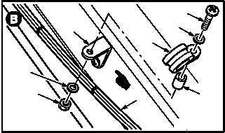
c. Remove clamp (7) from cable (8) and angle
bracket (9).
(1) Hold screw (10). Remove nut (11) and wash-
er (12).
(2) Remove screw (10), washer (12.1), clamp
(7), and spacer (12.2) from bracket (9).
(3) Remove clamp (7) from cable (8).
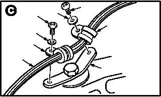
d. Remove two clamps (12.3) from cable (8) and
bracket (12.4).
(1) Remove two screws (12.5) and washers
(12.6) from bracket (12.4).
(2) Remove two clamps (12.3) from cable (8).
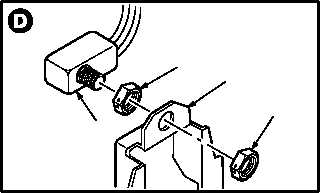
e. Remove lock switch assembly (13) from
switch tail bracket (14).
(1) Remove lockwire from nuts (15) and (16).
(2) Hold switch (13). Remove nut (15).
(3) Remove switch (13) and nut (16) from brack-
et (14).
(4) Remove nut (16) from switch (13). Discard
switch (13).
3.34.4. Cleaning
a. Wipe removed and attaching parts with a
clean rag.
3.34.5. Inspection
a. Check removed and attaching parts for dam-
aged. None allowed.
GO TO NEXT PAGE
M04-2341-3A
12
11
9
10
12.1
7
12.2
8
12.6
M04-2341-9
12.5
12.6
12.3
12.5
12.3
12.4
8
13
16
15
14
M04-2341-4


