TM 1-1520-238-23
3-120
Change 6
3.34.
TAIL LANDING GEAR ACTUATING CYLINDER LOCK SWITCH ASSEMBLY
REPLACEMENT – continued
3.34.6. Installation
NOTE
If replacement switched will not fit in
bracket, ream the hole in the bracket to
0.474 to 0.482 INCH to accommodate
new switch.
a. Install new switch (13) on bracket (14).
(1) Install nut (16) on switch (13).
(2) Install switch (13) and nut (16) on bracket
(14).
(3) Install nut (15) on switch (13). Do not tighten
nuts.
b. Adjust switch (13).
(1) Adjust nuts (15) and (16) to move switch (13)
to obtain 0.040 to 0.060 INCH gap between
sensor (18) and target (19).
(2) Tighten nuts (15) and (16).
(3) Lockwire nut (15) to nut (16). Use wire
(item 224, App F).
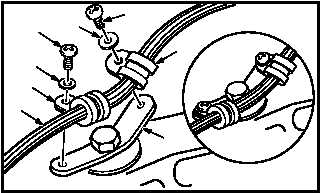
c. Install two clamps (12.3) on cable (8) and
bracket (12.4).
(1) Install two clamps (12.3) on cable (8).
(2) Install two screws (12.5) through washers
(12.6), clamps (12.3), and bracket (12.4).
GO TO NEXT PAGE
16
13
14
15
M04-2341-8
13
16
15
18
19
M04-2341-5
14
19
0.040 TO
0.060 IN
M04-2341-10
12.6
12.5
12.6
12.3
12.5
12.3
12.4
8