TM 1-1520-238-23
Change 1
4-503
4.151.
COLLECTIVE SERVOCYLINDER ENGINE CONTROL ROD REMOVAL/INSTALLATION – continued
4.151.6. Installation
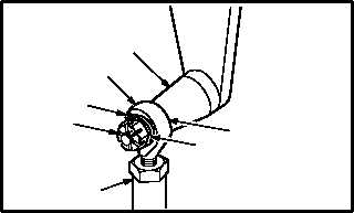
a. Install rod (1) on adapter (7). Torque nut (9) 14
to 18 INCH-POUNDS.
(1) Install washer (12) on adapter (7).
(2) Slide rod end (11) on adapter (7).
(3) Install washer (10) and nut (9) on adapter (7).
Torque nut (9) to 14 INCH-POUNDS. Use
torque wrench.
(4) Increase torque to aline cotter pin hole, but do
not exceed 18 INCH-POUNDS.
(5) Install new cotter pin (8).
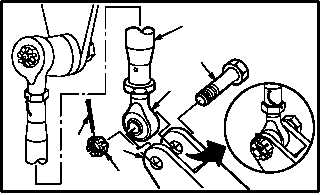
b. Install servocylinder (1) on bellcrank (2).
Torque nut (5) 14 to 18 INCH-POUNDS.
(1) Hold open end of bellcrank (2) full down.
(2) Aline rod end (6) to bellcrank (2).
(3) Install bolt (4) through bellcrank (2) and rod
end (6).
(4) Check fit of self-retaining bolt (4) (para 11.1).
(5) Install nut (5) on bolt (4). Torque nut (5) to 14
INCH-POUNDS. Use torque wrench.
(6) Increase torque to aline cotter pin hole, but do
not exceed 18 INCH-POUNDS.
(7) Install new cotter pin (3).
GO TO NEXT PAGE
1
9
10
7
M04-2316-6
8
11
12
3
5
6
4
2
M04-2316-10
1