TM 1-1520-238-23
Change 1
4-500.1/(4-500.2 blank)
4.150.
NO. 1 OR NO. 2 ENGINE LOAD DEMAND SPINDLE FORWARD CABLE
INSTALLATION – continued
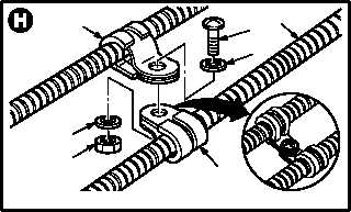
j. On No. 1 engine, install clamp (52) on cable
(2).
(1) Position clamps (52) on cable (2).
(2) Install screw (53) through washer (54) and
two clamps (52).
(3) Hold screw (53). Install washer (55) and nut
(56).
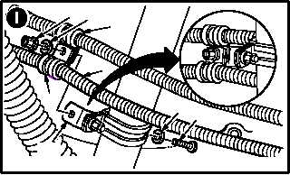
k. On No. 2 engine, install clamp (57) on cable
(2).
(1) Position clamp (57) on cable (2).
(2) Install screw (58) through washer (59), brack-
et (60), and clamps (61) and (57).
(3) Hold screw (58). Install washer (62) and nut
(63).
l. Inspect (QA).
m. Perform No. 1 or No. 2 load demand spindle
rigging check (para 4.184).
n. Install access panel L200 for No. 1 engine;
secure access panel R200 and doors RN1,
T250L, T250R, T290L, T290R, and L325 for No.
2 engine (para 2.2).
END OF TASK
M04-1188-26
53
54
2
52
55
56
52
NO. 2 ENGINE LDS CABLE
57
63
2
M04-1188-27
5958
61
62
60
NO. 2 ENGINE LDS CABLE