TM 1-1520-238-23
4-500
Change 1
4.150.
NO. 1 OR NO. 2 ENGINE LOAD DEMAND SPINDLE FORWARD CABLE
INSTALLATION – continued
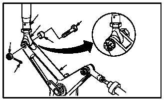
g. Install rod (24) on bellcrank (25). Torque nut
(28) 14 to 18 INCH-POUNDS.
(1) Aline rod end (30) to bellcrank (25).
(2) Install bolt (27) through bushing (29), bell-
crank (25) and rod end (30).
(3) Hold bolt (27). Install nut (28). Torque nut (28)
to 14 INCH-POUNDS. Use torque wrench.
(4) Increase torque to aline cotter pin hole, but do
not exceed 18 INCH-POUNDS.
(5) Install new cotter pin (26).
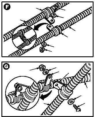
h. On No. 1 and No. 2 engine install two clamps
(40) on cables (2) and (41).
(1) Position clamps (40) on cable (2) and cable
(41).
(2) Install screw (42) through washer (43) and
two clamps (40).
(3) Hold screw (42). Install washer (44) and nut
(45).
i. On No. 1 engine, install two clamps (46) on
cables (2) and (47).
(1) Position clamps (46) on cables (2) and (47).
(2) Install screw (48) through washer (49) and
two clamps (46).
(3) Hold screw (48). Install washer (50) and nut
(51).
GO TO NEXT PAGE
26
28
24
30
29
25
27
M04-1188-24
M04-1188-25
44
42
43
45
40
40
2
41
46
51
2
49
48
NO. 1 ENGINE LDS CABLE
46
50
M04-1188-29
47


