TM 1-1520-238-23
4-513
4.154.
ENGINE LOAD DEMAND SPINDLE BELLCRANK REMOVAL/INSTALLATION – continued
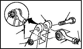
d. Install cable (1) on bellcrank (2). Torque nut (5)
14 to 18 INCH-POUNDS.
(1) Aline rod end (6) on bellcrank (2).
(2) Install bolt (4) through bellcrank (2) and rod
end (6).
(3) Install nut (5) on bolt (4). Torque nut (5) to 14
INCH-POUNDS. Use torque wrench.
(4) Increase torque to aline cotter pin hole, but do
not exceed 18 INCH-POUNDS.
(5) Install new cotter pin (3).
e. Inspect (QA).
f. Perform No. 1 and No. 2 engine load demand
spindle rigging check (para 4.184).
g. Perform power plants maintenance operation-
al
check
(engine
1
and
engine
2)
(TM 1-1520-238-T).
h. Secure access panel L200 (para 2.2).
END OF TASK
6
2
3
4
5
1
M04-2317-10

