TM 1-1520-238-23
4-541
4.162.
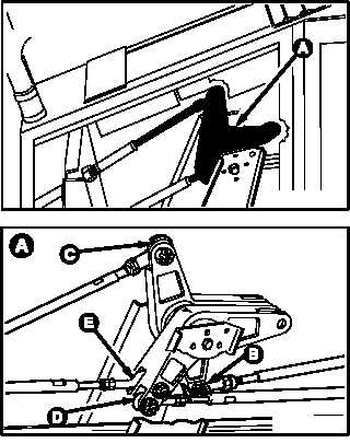
PILOT POWER AVAILABLE SPINDLE BELLCRANKS REMOVAL/INSTALLATION
4.162.1. Description
This task covers:
Removal. Cleaning. Inspection. Installation.
4.162.2. Initial Setup
Tools:
Aircraft mechanic’s tool kit (item 376, App H)
0.001 - 0.200-inch dial indicator (item 176, App H)
0 - 30 inch-pound 1/4-inch drive dial indicator torque
wrench (item 445, App H)
0 - 75 inch-pound 1/4-inch drive dial indicator torque
wrench (item 446, App H)
Materials/Parts:
Cotter pin (5)
Personnel Required:
67R
Attack Helicopter Repairer
67R3F
Attack Helicopter Repairer/Technical
Inspector
References:
TM 1-1500-204-23
Equipment Conditions:
Ref
Condition
1.57
Helicopter safed
9.62
EXT LT/INTR LT panel removed
10.54
Pilot FUEL panel removed
4.166
Pilot power quadrant removed
2.2
Console panel PL5 removed
WARNING
To prevent injury to personnel, ensure
that CPG power quadrant levers do
not move during procedure. If injury
occurs, seek medical aid.
4.162.3. Removal
a. Enter pilot station (para 1.56). Observe all
safety precautions.
b. Check for radial play with bolt in bellcrank
clevis hole. Not to exceed 0.004 INCH. Use dial
indicator (TM 1-1500-204-23).
c. Check for radial play in ball bearing. Not to
exceed 0.004 INCH. Use dial indicator
(TM 1-1500-204-23).
GO TO NEXT PAGE
M04-3560-1
M04-3560-13