TM 1-1520-238-23
4-546
4.162.
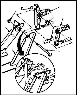
PILOT POWER AVAILABLE SPINDLE BELLCRANKS REMOVAL/INSTALLATION – continued
h. Install bellcranks (6) and (15). Torque nut (3) 30
to 40 INCH-POUNDS.
(1) Aline bellcrank (15) with inboard support (23).
(2) Install bolt (1) through inboard support (23)
and bellcrank (15).
(3) Install spacer (2) on bolt (1) against bellcrank
(15).
(4) Aline bellcrank (6) between spacer (2) and
outboard support (24).
(5) Install bolt (1) through bellcrank (6) and out-
board support (24).
(6) Install nut (3) on bolt (1).
(7) Hold bolt (1). Torque nut (3) to 30 INCH-
POUNDS. Use torque wrench.
(8) Increase torque to aline cotter pin hole, but do
not exceed 40 INCH-POUNDS.
i. Check radial play with bolt in bellcrank clevis
hole. Not to exceed 0.004 INCH. Use dial
indicator (TM 1-1500-204-23).
j. Check radial play in ball bearing. Not to exceed
0.004
INCH.
Use
dial
indicator
(TM 1-1500-204-23).
GO TO NEXT PAGE
M04-3560-7
3
2
1
15
6
24
23