TM 1-1520-238-23
4-543
4.162.
PILOT POWER AVAILABLE SPINDLE BELLCRANKS REMOVAL/INSTALLATION – continued
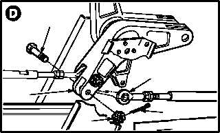
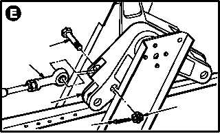
h. Remove forward rod end (14) from No. 2 bell-
crank (15).
(1) Remove and discard cotter pin (16).
(2) Hold bolt (17). Remove nut (18).
(3) Remove bolt (17).
i. Remove aft rod end (19) from bellcrank (15).
(1) Remove and discard cotter pin (20).
(2) Hold bolt (21). Remove nut (22).
(3) Remove bolt (21).
j. Remove bellcrank (15).
4.162.4. Cleaning
a. Clean removed and attaching parts (para
1.47).
4.162.5. Inspection
a. Check bellcranks for cracks and corrosion.
None allowed.
b. Check bellcranks for damage. Up to 0.015
INCH maximum must be blended out
(TM 1-1500-204-23).
c. Check bellcranks for corrosion (para 1.49).
4.162.6. Installation
NOTE
For No. 2 bellcrank installation, go to step
d.
a. Perform self-retaining bolt fit check (para
11.1).
GO TO NEXT PAGE
17
15
18
14
16
M04-3560-4
M04-3560-5
21
19
15
20
22