TM 1-1520-238-23
4-556
Change 5
4.166.
PILOT POWER QUADRANT REMOVAL/INSTALLATION
4.166.1. Description
This task covers:
Removal. Cleaning. Inspection. Installation.
4.166.2. Initial Setup
Tools:
Aircraft mechanic’s tool kit (item 376, App H)
7/8 x 3/8-inch drive open end box socket wrench
crowfoot attachment (item 86, App H)
0 - 30 inch-pound 1/4-inch drive dial indicator torque
wrench (item 445, App H)
Materials/Parts:
Cotter pin (2)
Personnel Required:
67R
Attack Helicopter Repairer
67R3F
Attack Helicopter Repairer/Technical
Inspector
References:
TM 1-1520-238-T
TM 55-1500-323-24
Equipment Conditions:
Ref
Condition
1.57
Helicopter safed
2.2
Console panels PL1 and PL3 removed
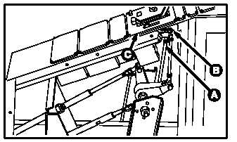
NOTE
This task is typical for removal of both
pilot power quadrants (P/N 53065-11 and
P/N C82051-1). P/N 53065-11 is illus-
trated.
4.166.3. Removal
a. Enter pilot station (para 1.56). Observe all
safety precautions.
b. On pilot forward circuit breaker panel, open
EMER HYD, RTR BRK, and LT ENG START
circuit breakers.
c. On pilot center circuit breaker panel, open LT
PRI circuit breaker.
GO TO NEXT PAGE
M04-1195-2
PILOT STATION