TM 1-1520-238-23
4-666
Change 4
4.184.
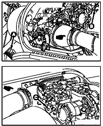
NO. 1 OR NO. 2 ENGINE LOAD DEMAND SPINDLE RIGGING CHECK
4.184.1. Description
This task covers:
Rigging check.
4.184.2. Initial Setup
Tools:
Aircraft mechanic’s tool kit (item 376, App H)
Flight control rigging kit (item 267, App H)
Aircraft power unit (item 232, App H)
10 - 50 inch-pound 1/4-inch drive click type torque
wrench (item 434, App H)
Materials/Parts:
Cotter pin
Wire (item 226, App F)
Personnel Required:
67R
Attack Helicopter Repairer
One person to assist
67R3F
Attack Helicopter Repairer/Technical
Inspector
References:
TM 1-1520-238-T
Equipment Conditions:
Ref
Condition
1.57
Helicopter safed
1.70
External power application – electrical
1.72
External power application – hydraulic (pri-
mary)
2.2
Access doors LN1 and RN1 opened; panel
L200 removed
4.103
No. 1 or No. 2 engine shroud assembly re-
moved
NOTE
This task is typical for Hamilton Stan-
dard and Woodward hydromechanical
units (HMUs).
This task is typical for T700-GE-701
and T700-GE-701C engines.
This task is typical for No. 1 or No. 2
load demand spindle rigging check.
4.184.3. Rigging Check
a. Enter pilot station (para 1.56). Observe all
safety precautions.
GO TO NEXT PAGE
M04-1209-1A
NO. 1 ENGINE
M04-1209-10A
NO. 2 ENGINE


