TM 1-1520-238-23
4-662
Change 1
4.183.
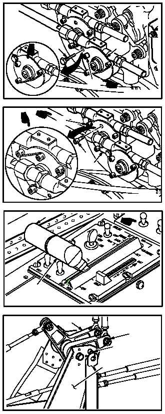
NO. 2 ENGINE POWER AVAILABLE SPINDLE (PAS) RIGGING PROCEDURE – continued
ak. Stow rig pin (20) in gearbox (21).
(1) Lockwire rig pin (20) to cap screw (36). Use
wire (item 226, App F).
al. Install cap screw (22) in gearbox (18).
(1) Lockwire cap screws (22) and (37) together.
Use wire (item 226, App F).
am. Move power levers (3) and (7) to IDLE posi-
tion.
an. At pilot station, install –3 rig pin (8) in bracket
(9) and bellcranks (10) and (11).
GO TO NEXT PAGE
M04-1208-37A
20
21
36
M04-1208-38A
18
22
37
M04-1208-51A
7
3
11
10
M04-1208-52
8
9