TM 1-1520-238-23
4-670
Change 6
4.184.
NO. 1 OR NO. 2 ENGINE LOAD DEMAND SPINDLE RIGGING CHECK – continued
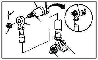
v. Install rod end (6) on adapter (7). Torque nut (9)
to 30 to 40 INCH-POUNDS.
(1) Position rod end (6) on adapter (7).
(2) Install nut (9) on adapter (7).
(3) Hold adapter (7), torque nut (9) to 30 INCH-
POUNDS. Use torque wrench.
(4) Increase torque to aline cotter pin hole, but do
not exceed 40 INCH-POUNDS.
(5) Install new cotter pin (8).
w. Inspect (QA).
x. Install No. 1 or No. 2 engine shroud assembly
(para 4.103).
y. Secure access doors LN1 and RN1; install
panel L200 (para 2.2).
z. Perform power plants maintenance operation-
al check (engine 1 and engine 2)
(TM 1-1520-238-T).
END OF TASK
6
7
M04-1209-16
8
9