TM 1-1520-238-23
Change 4
4-673
4.185.
NO. 1 AND NO. 2 ENGINE LOAD DEMAND SPINDLE RIGGING – continued
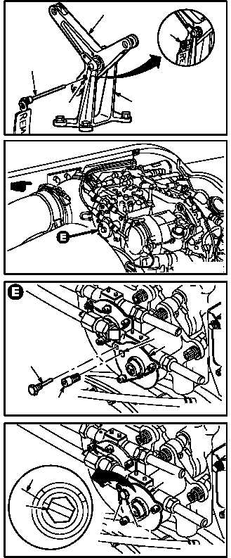
d. Install –7 rig pin (15) in bracket (16) and bell-
crank (2) at bottom rig pin hole (17).
e. Remove rig pin (18) from No. 2 engine LDS
gearbox (19).
(1) Remove lockwire from pin (18).
(2) Remove rig pin (18).
f. Remove cap screw (20) from gearbox (19).
NOTE
Rig pin must bottom and lock gearbox at
zero degree position.
g. Install rig pin (18) in gearbox (19) at zero de-
gree rig pin hole (21).
(1) Rotate gearbox shaft (22) as required to aline
rig pin hole (21).
(2) Install rig pin (18) in rig pin hole (21).
GO TO NEXT PAGE
M04-1210-6
15
2
15
17
16
M04-1210-7A
M04-1210-8
18
20
19
21
22
0 DEGREES
19
M04-1210-9
21
18

