TM 1-1520-238-23
4-674
Change 4
4.185.
NO. 1 AND NO. 2 ENGINE LOAD DEMAND SPINDLE RIGGING – continued
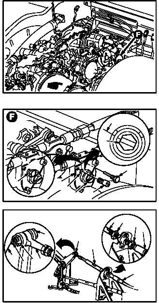
h. Remove rig pin (23) from No. 1 engine LDS
gearbox (24).
(1) Remove lockwire from pin (23).
(2) Remove pin (23).
i. Remove cap screw (25) from gearbox (24).
NOTE
Rig pin must bottom and lock gearbox at
zero degree position.
j. Install rig pin (23) in gearbox (24) at zero de-
gree position.
(1) Turn gearbox shaft (26) as required to aline
rig pin hole (27).
(2) Install rig pin (23) in rig pin hole (27).
k. Install cable rod end (1) to bellcrank (2).
Torque nut (5) 14 to 18 INCH-POUNDS.
(1) Hold cable (28) on flats (29). Loosen nuts
(30) and (31).
(2) Adjust cable (28) to aline rod end (1) with
bellcrank (2).
(3) Install bolt (4) through bellcrank (2) and rod
end (1).
(4) Install nut (5) on bolt (4). Torque nut (5) to 14
INCH-POUNDS. Use torque wrench.
(5) Increase torque to aline cotter pin hole, but do
not exceed 18 INCH-POUNDS.
(6) Install new cotter pin (3).
GO TO NEXT PAGE
M04-1210-10A
M04-1210-11
23
25
26
24
26
0 DEGREES
23
27
M04-1210-12
2
3
51
4
1
29
29 3031
28
28


