TM 1-1520-238-23
4-677
4.185.
NO. 1 AND NO. 2 ENGINE LOAD DEMAND SPINDLE RIGGING – continued
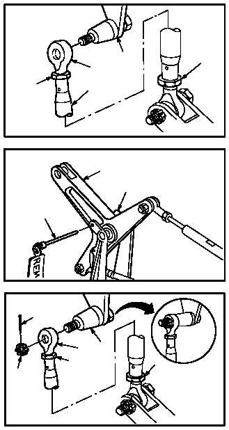
v. Aline link rod end (14) with adapter (11).
(1) Remove lockwire from nuts (38) and (39).
(2) Loosen nuts (38) and (39).
(3) Adjust rod (10) to aline rod end (14) with
adapter (11), but do not install.
w. Remove –7 rig pin (15) from bracket (16) and
bellcrank (2).
x. Check system for smooth operation.
(1) Move bellcrank (2) through full range of trav-
el.
y. Install link rod end (14) to adapter (11). Torque
nut (13) 30 to 40 INCH-POUNDS.
(1) Aline rod end (14) with adapter (11).
(2) Install nut (13) on adapter (11). Torque nut
(13) to 30 INCH-POUNDS. Use torque
wrench.
(3) Increase torque to aline cotter pin hole, but do
not exceed 40 INCH-POUNDS.
(4) Install new cotter pin (12).
(5) Torque nuts (38) and (39) to 20 INCH-
POUNDS. Use torque wrench.
(6) Lockwire nuts (38) and (39) to link (40). Use
wire (item 226, App F).
GO TO NEXT PAGE
14
11
M04-1210-20
38
10
39
16
M04-1210-21
2
15
14
11
M04-1210-23
12
13
38
39


