TM 1-1520-238-23
8-65
8.23.
PILOT/CPG ENGINE INSTRUMENT DIM/TEST CONTROL PANEL DISASSEMBLY/ASSEMBLY
(AVIM) – continued
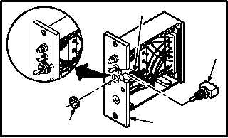
d. Install switch (7) in case (2).
(1) Attach three identified wires (8) to switch (7).
Use soldering iron and solder (item 189,
App F) (TM 55-1500-323-24).
(2) Insert switch (7) through case (2).
(3) Coat threads of switch (7). Use coating
compound (item 59, App F).
(4) Install nut (9) on switch (7).
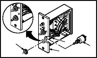
e. Install resistor (4) in case (2).
(1) Attach three identified wires (5) to resistor (4).
Use soldering iron and solder (item 189,
App F) (TM 55-1500-323-24).
(2) Install resistor (4).
(3) Coat threads of resistor (4). Use coating
compound (item 59, App F).
(4) Install nut (6) on resistor (4).
f. Inspect (QA).
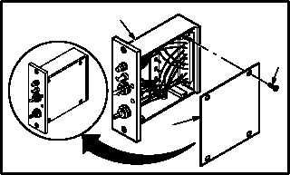
g. Install cover (1) on case (2). Torque four screws
(3) to 37 INCH-OUNCES.
(1) Position cover (1) on case (2).
(2) Coat threads of four screws (3). Use coating
compound (item 59, App F).
(3) Install four screws (3) through cover (1) into
case (2).
(4) Torque four screws (3) to 37 INCH-OUNCES.
Use torque wrench and screwdriver bit.
h. Install engine instrument dim/test control
panel front panel (para 8.24).
END OF TASK
2
9
7
M04-3544-10
8
2
6
4
5
M04-3544-11
M04-3544-12
3
1
2