TM 1-1520-238-23
9-72
9.20.
DC BUS ISOLATION DIODE REMOVAL/INSTALLATION
9.20.1. Description
This task covers:
Removal. Cleaning. Inspection. Installation.
9.20.2. Initial Setup
Tools:
Electrical tool kit (item 378, App H)
9/16 x 1/4-inch drive open end box socket wrench
crowfoot attachment (item 85, App H)
Ohmmeter (item 218, App H)
30 - 150 inch-pound 1/4-inch drive click type torque
wrench (item 435, App H)
Materials/Parts:
Silicone compound (item 185, App F)
Personnel Required:
68X
Armament/Electrical System Repairer
68X3F
Armament/Electrical System Repairer/
Technical Inspector
References:
TM 1-1520-238-T
TM 55-1500-323-24
Equipment Conditions:
Ref
Condition
1.57
Helicopter safed
9.9
Electrical power distribution box cover re-
moved
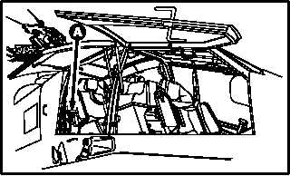
9.20.3. Removal
a. Enter pilot station (para 1.56). Observe all
safety precautions.
b On pilot aft circuit breaker panel, open six
POWER circuit breakers.
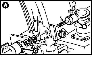
NOTE
The following step is typical for bus isola-
tion diodes CR1, CR2, CR3, and CR4.
c. Remove bus isolation diode (1) from bus con-
ductor (2).
(1) Remove nut (3), lockwasher (4), and flat
washer (5) from diode (1).
(2) Remove diode (1).
GO TO NEXT PAGE
M04-1417-1
1
2
M04-1417-5
34
5