TM 1-1520-238-23
9-533
9.138.
COAXIAL MASS TERMINATION CONNECTOR (MTC) REPAIR – continued
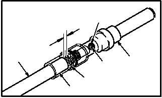
g. Check cable (8) and contact (6) for proper in-
sertion.
(1) Center conductor (15) must be visible
through forward inspection window (17).
(2) Distance from rear of contact body (18) to
outer jacket (12) must not exceed 0.10 INCH.
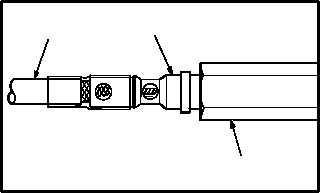
h. Insert contact (6) with cable (8) into repair
holding fixture (19).
(1) Cable (8) must be fully inserted into contact
(6).
(2) Contact (6) must be fully inserted into fixture
(19).
(3) Secure cable (8) and fixture (19) to prevent
movement during heating.
CAUTION
Secure cable during heating to prevent
“cold” solder joints. Be sure to allow sol-
der to solidify at least 15 seconds before
removing contact from holding fixture.
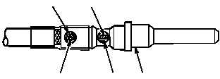
i. Heat contact (6). Use heating tool kit and
nitrogen (item 128, App F) if on helicopter.
(1) Direct heat at forward inspection window (17)
until solder (20) melts and flows. Use solder
(item 189, App F).
(2) Direct heat at rear inspection window (21)
until solder (22) melts and flows.
j. After cooling, check contact (6) for proper
position and good solder joints.
k. Perform continuity check. Use multimeter
(TM 55-1500-323-24).
GO TO NEXT PAGE
M04-3067-9
6
12
8
17
15
18
0.10 IN MAX
19
8
6
M04-3067-16
5
17
22
21
20
M04-3067-10