TM 1-1520-238-23
10-514
10.123.
NITROGEN INERTING MONITOR PANEL REMOVAL/INSTALLATION
10.123.1. Description
This task covers:
Removal. Cleaning. Inspection. Installation.
10.123.2. Initial Setup
Tools:
Electrical tool kit (item 378, App H)
Light duty laboratory apron (item 27, App H)
Chemical protective gloves (item 154, App H)
Adjustable air filtering respirator (item 262, App H)
Soldering gun (item 334, App H)
Materials/Parts:
Solder (item 189, App F)
Personnel Required:
68X
Armament/Electrical System Repairer
68X3F
Armament/Electrical System Repairer/
Technical Inspector
References:
TM 1-1520-238-T
TM 55-1500-323-24
Equipment Conditions:
Ref
Condition
1.57
Helicopter safed
10.2
Fuel system safety precautions observed
2.2
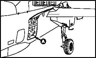
Access door R295 opened; access panel
R200 removed
10.123.3. Removal
a. Enter pilot station (para 1.56). Observe all
safety precautions.
b. On pilot center circuit breaker panel, open
ENG INST, FUEL XFEED, and FUEL XFER cir-
cuit breakers.
c. In upper right corner of utility receptacle cir-
cuit breaker panel in main rotor transmission
compartment R200, open NITROGEN INERT
circuit breaker.
GO TO NEXT PAGE
M04-2977-1
M04-2977-2


