TM 1-1520-238-23
10-516
10.123.
NITROGEN INERTING MONITOR PANEL REMOVAL/INSTALLATION – continued
10.123.5. Inspection
a. Check nitrogen inerting monitor panel for
cracks, nicks, dents, and readability of mark-
ings (para 10.1).
b. Check reset indicator and switch for general
condition.
c. Check terminal posts and switch for cracks,
breaks, and looseness (para 10.1).
d. Check lugs of indicator for cracks, breaks,
and looseness.
e. Check wires of press-to-test switch and wires
of reset indicator for frayed or damaged in-
sulation (para 10.1).
10.123.6. Installation
WARNING
Soldering iron can cause severe
burns to personnel and start fires.
Observe all safety precautions when
using soldering iron. If injury occurs,
seek medical aid.
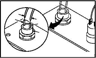
a. Solder two identified wires (10) to indicator (4)
(TM 55-1500-323-24).
(1) Solder two wires (10) to lugs (11). Use
soldering gun and solder (item 189, App F).
GO TO NEXT PAGE
10
11
10
4
11
M04-2977-7


