TM 1-1520-238-23
11-217
11.44.
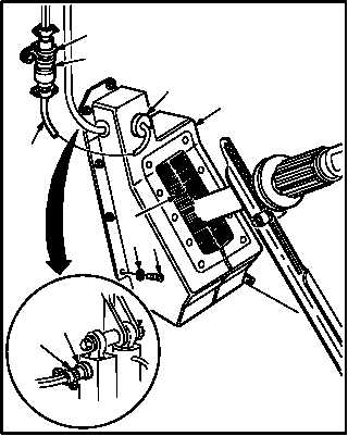
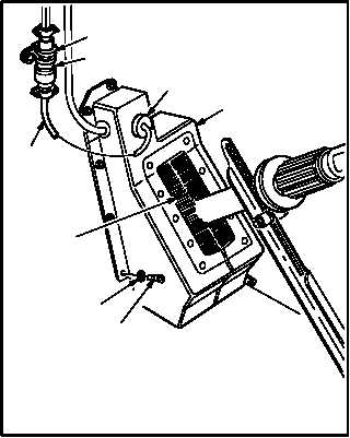
COLLECTIVE STICK COVER REMOVAL/INSTALLATION – continued
11.44.6. Installation
a. Install cover (3).
(1) Position LVDT cable (7) in grommet (6).
(2) Install grommet (6) in cover (3).
(3) In pilot station, attach potentiometer cable
connector P1121 (8) to NR droop compensa-
tor receptacle (A656)J1 (9).
(4) Position cover (3).
(5) Install six screws (4) through washers (5) and
pilot cover (3).
(6) Install five screws (4) and washers (5) on
CPG cover (3).
b. In pilot station, attach receptacle J230 (1) to
connector P230 (2).
c. In CPG station, attach receptacle J234 (1) to
connector P234 (2).
d. Inspect (QA).
END OF TASK
PILOT STATION
M04-2960-5
8
9
5
4
9
3
2
1
7
6
CPG STATION
M04-2960-6
5
4
9
3
2
1
7
6