TM 1-1520-238-23
4-496
Change 1
4.150.
NO. 1 OR NO. 2 ENGINE LOAD DEMAND SPINDLE FORWARD CABLE
INSTALLATION – continued
NOTE
Do not apply silicone compound to sup-
port tube.
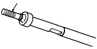
f. Lubricate sliding rod (2.3) end at seal contact
area. Use silicone compound (item 186, App F).
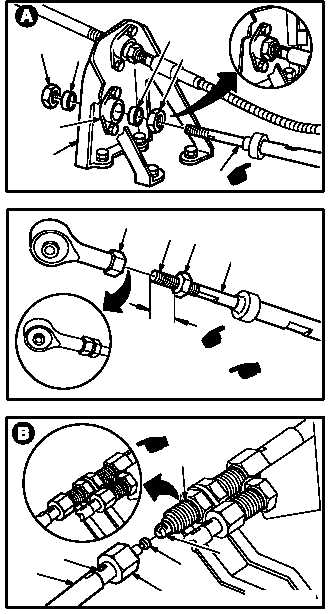
g. Install engine LDS forward cable (2) on sup-
port (3).
(1) Center nut (4) on threaded area of cable (2).
(2) Install spacer (5) on cable (2).
(3) Slide cable (2) through support bearing (6).
(4) Install spacer (7) on cable (2).
(5) Install nut (8) on cable (2) and tighten until
spacer (7) contacts bearing (6).
h. Install rod end (9) on cable (2). Torque nut (10)
to 20 INCH-POUNDS.
(1) Install nut (10) on cable (2) so 0.50 INCH of
threaded cable end is exposed.
(2) Install rod end (9) 0.50 INCH on cable
threads (11).
(3) Hold rod end (9). Torque nut (10) to 20 INCH-
POUNDS. Use torque wrench, crowfoot, and
adapter.
i. On No. 1 engine, install cable (2) on aft cable
(13). Torque coupling nut (14) to 70 INCH-
POUNDS.
(1) Install fitting (15) on fitting (16).
(2) Install coupling nut (14) on cable (13).
(3) Hold cable (2) at flats (2.4). Torque nut (14) to
70 INCH-POUNDS. Use torque wrench,
crowfoot, and adapter.
GO TO NEXT PAGE
2.3
M04-1188-5
M04-1188-14A
NO. 2 ENGINE LDS CABLE
2
8
7
6
5
4
3
11
M04-1188-15A
10
2
1/2
IN
9
TYPICAL FOR NO. 1
AND NO. 2 ENG
NO. 1 ENGINE LDS CABLE
M04-1188-6A
2
2.4
13
14
15
16