TM 1-1520-238-23
Change 1
4-497
4.150.
NO. 1 OR NO. 2 ENGINE LOAD DEMAND SPINDLE FORWARD CABLE
INSTALLATION – continued
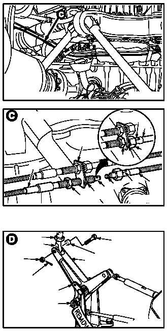
j. On No. 2 engine, install cable (2) on support
bracket (18). Torque coupling nut (19) to 70
INCH-POUNDS and nuts (20) and (21) to 90
INCH-POUNDS.
(1) Install nut (20) on cable (2).
(2) Install cable (2) through bracket (18).
(3) Install nut (21) three turns on cable (2).
(4) Adjust nuts (20) and (21) to aline fitting (15)
with fitting (16).
(5) Install fitting (16) on fitting (15).
(6) Install coupling nut (19) on cable (2).
(7) Torque nuts (20) and (21) to 90 INCH-
POUNDS. Use torque wrench, crowfoot, and
adapter.
(8) Hold aft cable (22) at flats (23). Torque cou-
pling nut (19) to 70 INCH-POUNDS. Use
torque wrench, crowfoot, and adapter.
k. Inspect (QA).
l. Remove rod (24) from bellcrank (25).
(1) Remove and discard cotter pin (26).
(2) Hold bolt (27). Remove nut (28).
(3) Remove bolt (27) and bushing (29) from bell-
crank (25) and rod end (30).
m. Install –5 rigging pin (31).
(1) Aline lower hole in bellcrank (25) with lower
hole in bracket (32).
(2) Install –5 rig pin in bracket (32) and bellcrank
(25).
GO TO NEXT PAGE
M04-1188-16
NO. 2 ENGINE LDS CABLE
23
16
18
20
2115
22
M04-1188-17
NO. 2 ENGINE LDS CABLE
2
23
22
19
21
20
24
30
28
26
27
29
25
32
31
M04-1188-18