TM 1-1520-238-23
4-648
Change 1
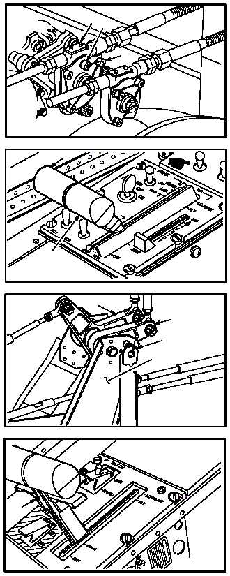
4.182.
NO. 1 ENGINE POWER AVAILABLE SPINDLE (PAS) RIGGING PROCEDURE – continued
al. Install cap screw (22) in gearbox (18).
am. Lockwire cap screws (22) and (37) together.
Use wire (item 226, App F).
an. Set pilot power levers (3) and (7) to IDLE.
ao. At pilot station, install –3 rig pin (8) fully in
bracket (9) and bellcranks (10) and (11).
ap. Verify power lever (6) is in IDLE position.
NOTE
If CPG power lever alines with IDLE posi-
tion, go to step ax.
GO TO NEXT PAGE
M04-1207-37A
1822
37
M04-1207-50A
3
7
11
10
M04-1207-51
8
9
6
M04-1207-52