TM 1-1520-238-23
9-35
9.9.
ELECTRICAL POWER DISTRIBUTION BOX COVER REMOVAL/INSTALLATION – continued
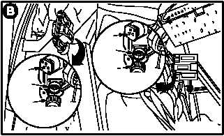
c. On pilot left sensor surveyor unit (14), detach
connector P929 (15) from receptacle (A608)J1
(16).
d. On pilot right sensor surveyor unit (17), de-
tach connector P927 (18) from receptacle
(A606)J1 (19).
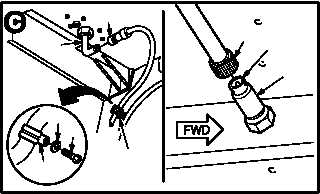
e. On horizontal accelerometer (20), detach con-
nector P56 (21) from connector MT31 (22).
f. Detach connector P388 (23) from antenna re-
ceptacle (E310)J388 (24).
g. Remove screw (25), washer (26), and clamp
(27) from bracket (28).
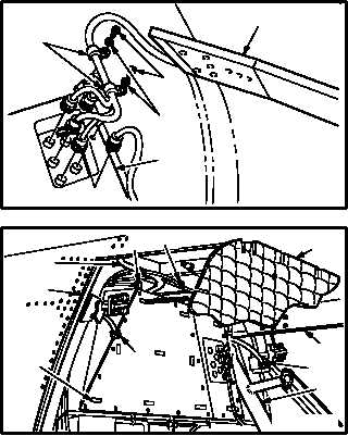
h. Remove two screws (29), washers (30), and
clamps (31) from pilot bulkhead (32).
i. Remove thermal insulation (33) from airframe
(34).
(1) Unlock hook-and-pile fasteners (35).
(2) Remove insulation (33) from around environ-
mental control system duct (36), defog tube
(37), and defog tube (38).
(3) Slide insulation (33) off connectors P929
(15), P927 (18), P56 (21), and P388 (23).
GO TO NEXT PAGE
14
16
15
VIEW
ROTATED
M04-3327-3
17
19
18
VIEW
ROTATED
26
27
25
24
23
28
21
22
20
M04-3327-4
M04-3327-12
31
29
30
32
PILOT C/B PANEL
18
38
34
23
21
35
36
15
37
33
M04-3327-5