TM 1-1520-238-23
9-37
9.9.
ELECTRICAL POWER DISTRIBUTION BOX COVER REMOVAL/INSTALLATION – continued
b. Install thermal insulation (33) on airframe (34).
(1) Insert connector P929 (15) through cutout
(42) in insulation (33).
(2) Insert connector P56 (21) through cutout (43)
in insulation (33).
(3) Insert connector P927 (18) through cutout
(44) in insulation (33).
(4) Insert connector P388 (23) through cutout
(45) in insulation (33).
(5) Aline insulation (33) with airframe (34) and
lock hook-and-pile fasteners (35).
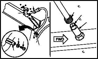
c. Attach connector P56 (21) to connector MT31
(22) on horizontal accelerometer (20).
d. Attach connector P388 (23) to antenna recep-
tacle (E310)J388 (24).
e. Install clamp (27) on bracket (28).
(1) Aline clamp (27) with bracket (28).
(2) Install screw (25) through washer (26) and
clamp (27) in bracket (28).
f. Attach connector P927 (18) to receptacle
(A606)J1 (19) on pilot right sensor surveyor
unit (17).
g. Attach connector P929 (15) to receptacle
(A608)J1 (16) on pilot left sensor surveyor unit
(14).
GO TO NEXT PAGE
42
43
45
34
21
23
18
44
15
33
35
M04-3327-8
27
26
25
24
23
28
21
22
20
M04-3327-9
19
17
VIEW
ROTATED
18
15
16
14
VIEW
ROTATED
M04-3327-10